The Mitel SX-20 PABX
The Mitel SX-20 is a 72 line / 8 trunk Private Automatic Branch eXchange (PABX) from the early 1980s, designed and built in Canada. It features:
- 6809 processor running two banks of 48kB EPROM each (read about bank switching)
- analog crossbar (Mitel's own MT8804 chips, also designed and manufactured in Canada)
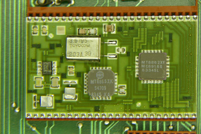
- dual DTMF decoders (Mitel's own hybrid chip design)
- POTS or SuperSet phone support
- SMDR output
- RMATS port
I have one running the phones in my house, and a lot of spare cards.
Click on the images below for more information, or the XL for the full size image.
Architecture
This diagram is a schematic representation of the overall layout of an SX-20 system.
The Hardware
The SX-20 consists of a CPU card, a Miscellaneous card, and a number of line cards and trunk modules.
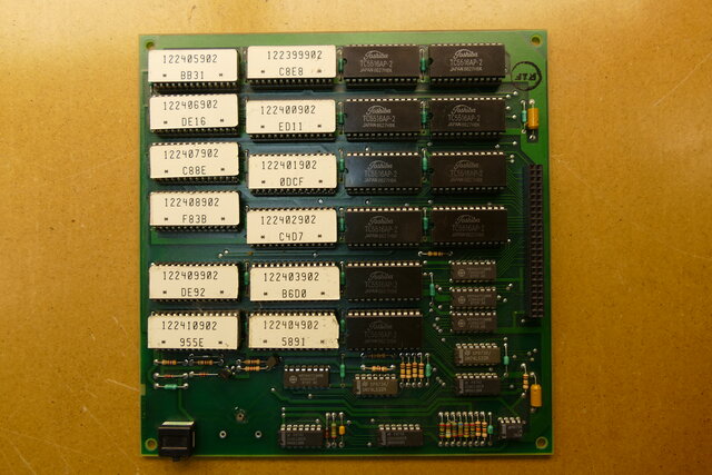
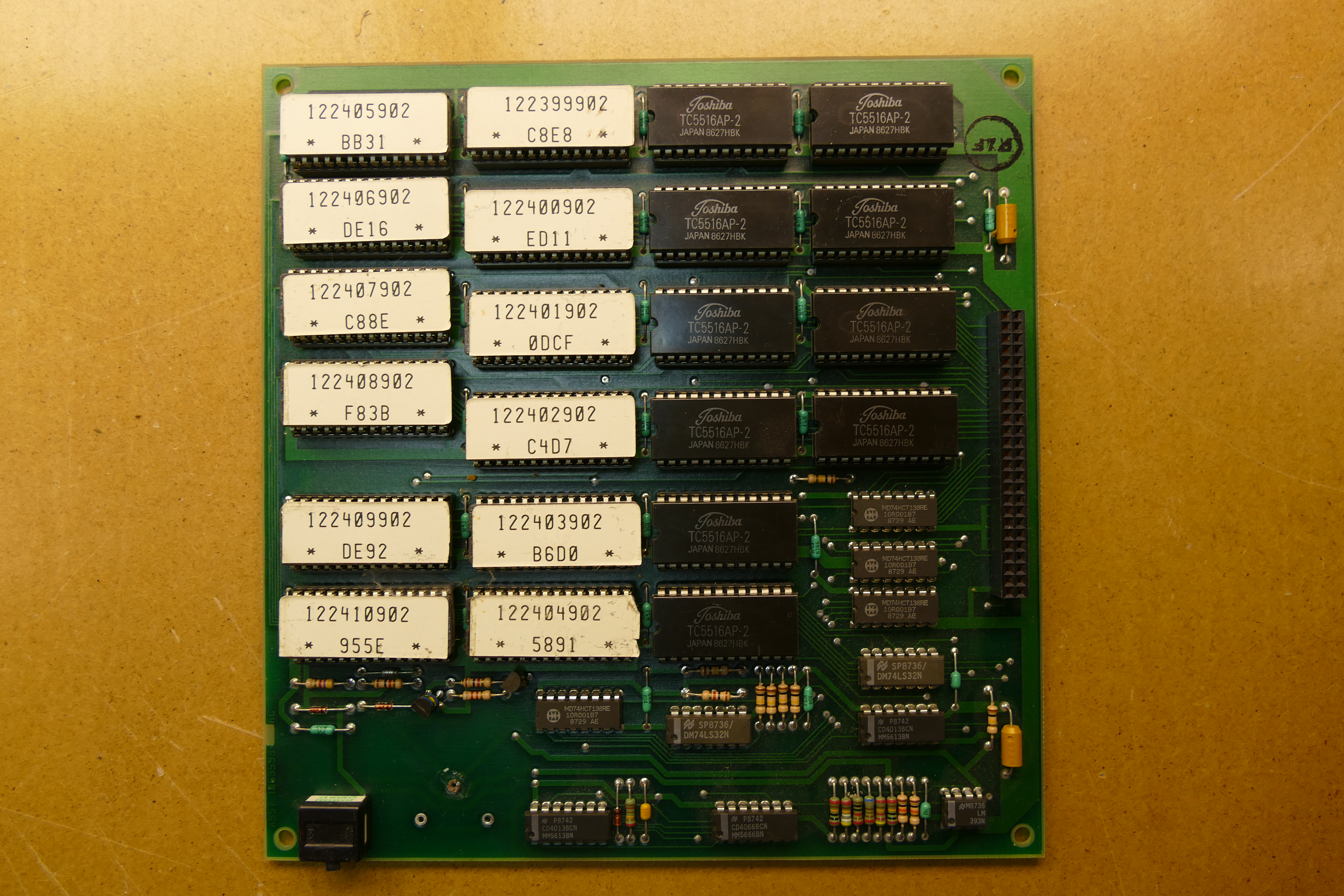
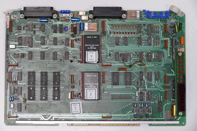
The CPU II
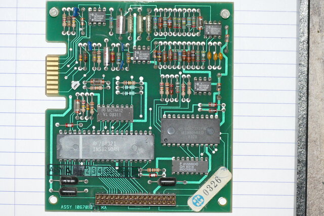
The SX-20 CPU card hosts a PROM card and an optional Remote Maintenance, Administration, and Test System (RMATS) card.


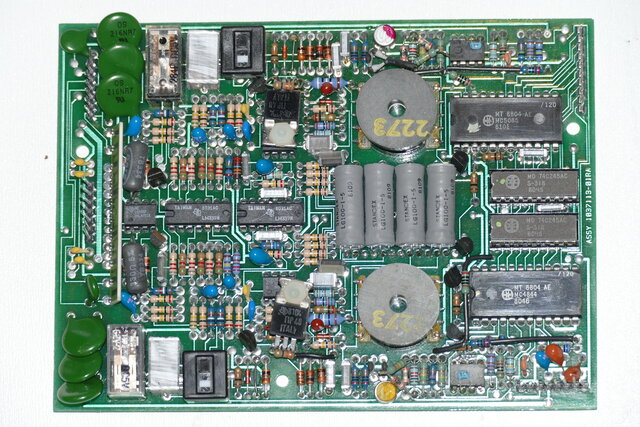
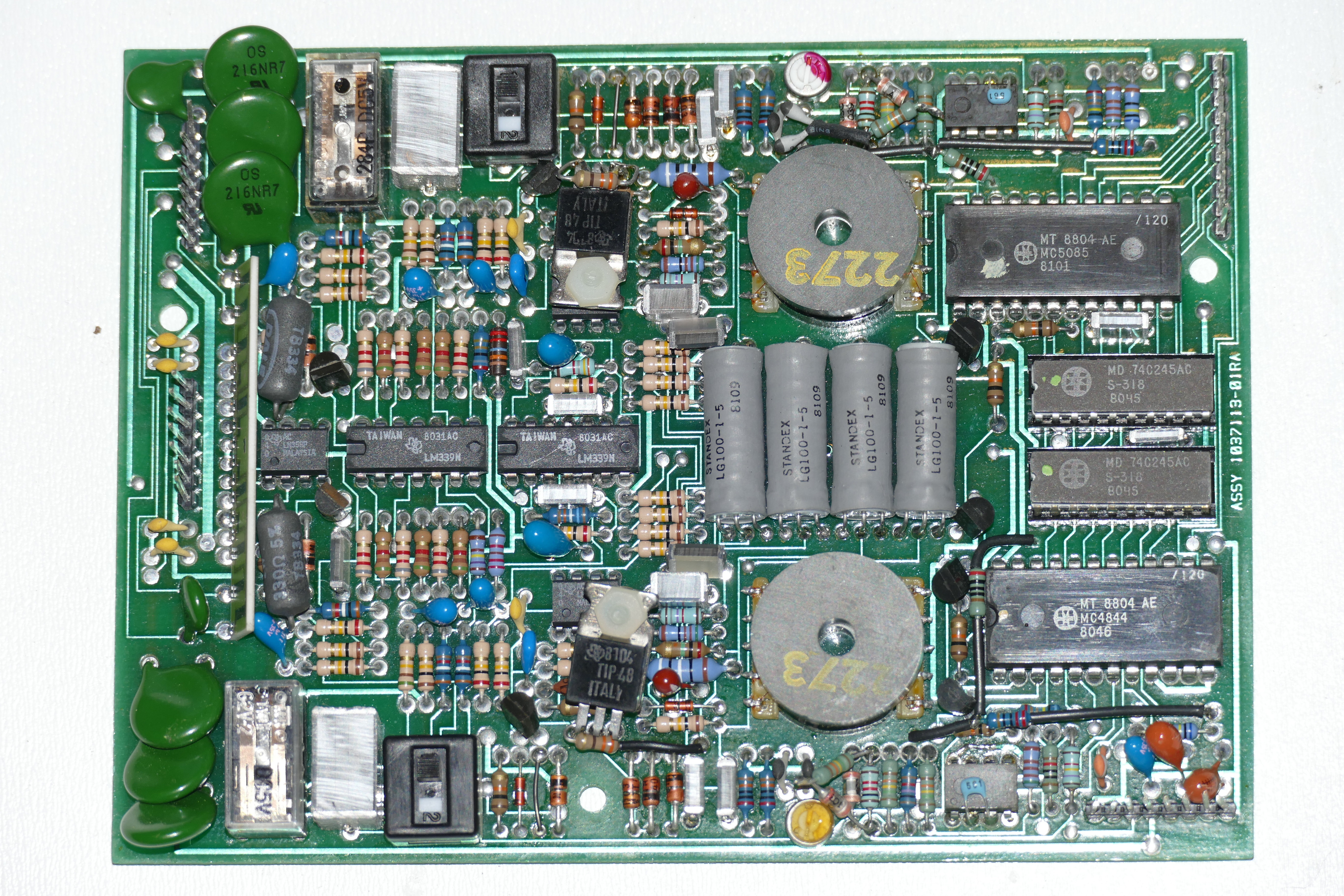
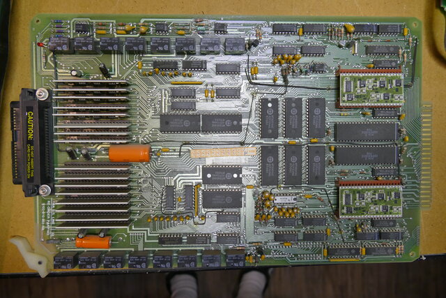
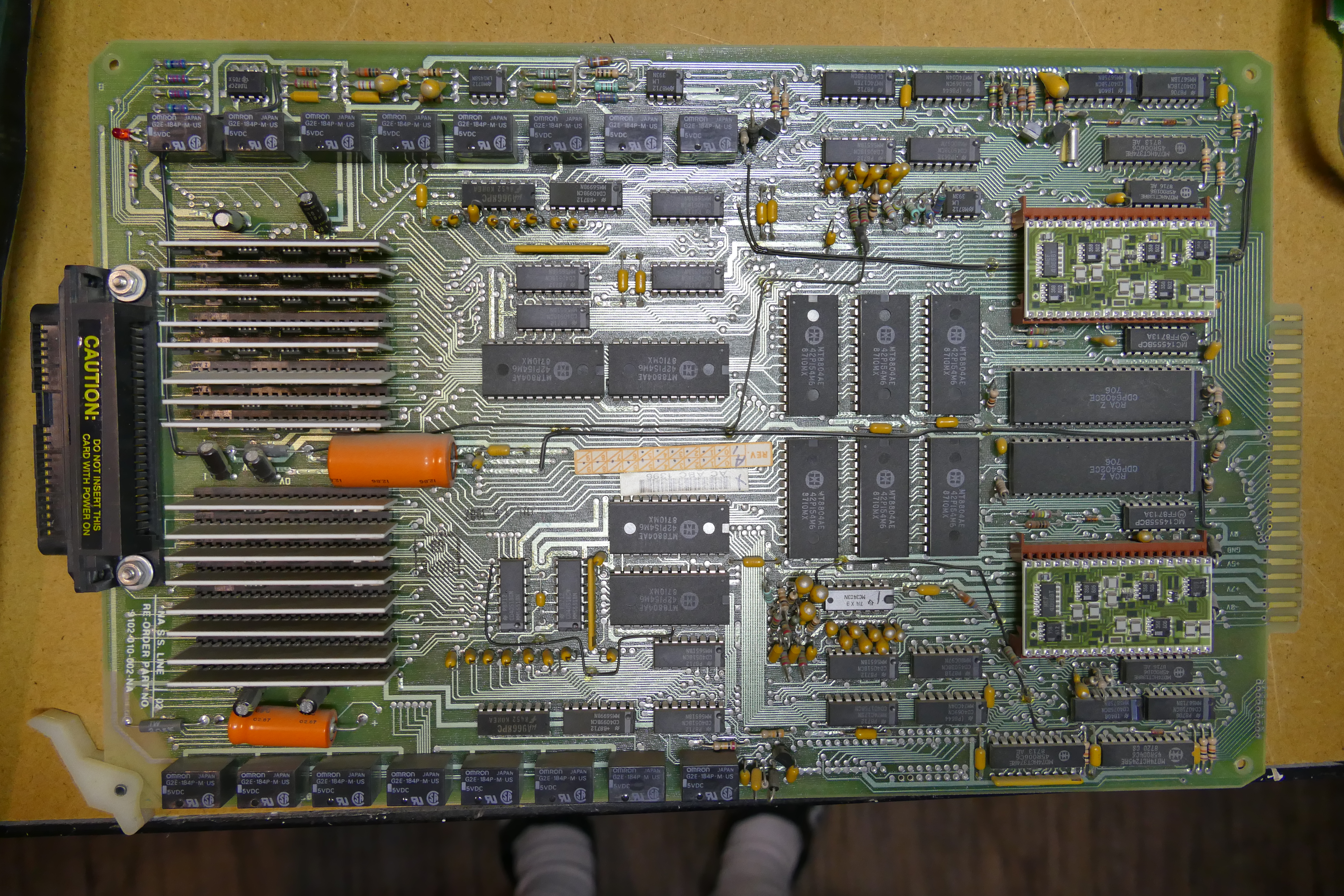
The Misc Card
The miscellaneous card hosts up to four trunk cards (serving two trunks each), and one or two DTMF receiver hybrids.


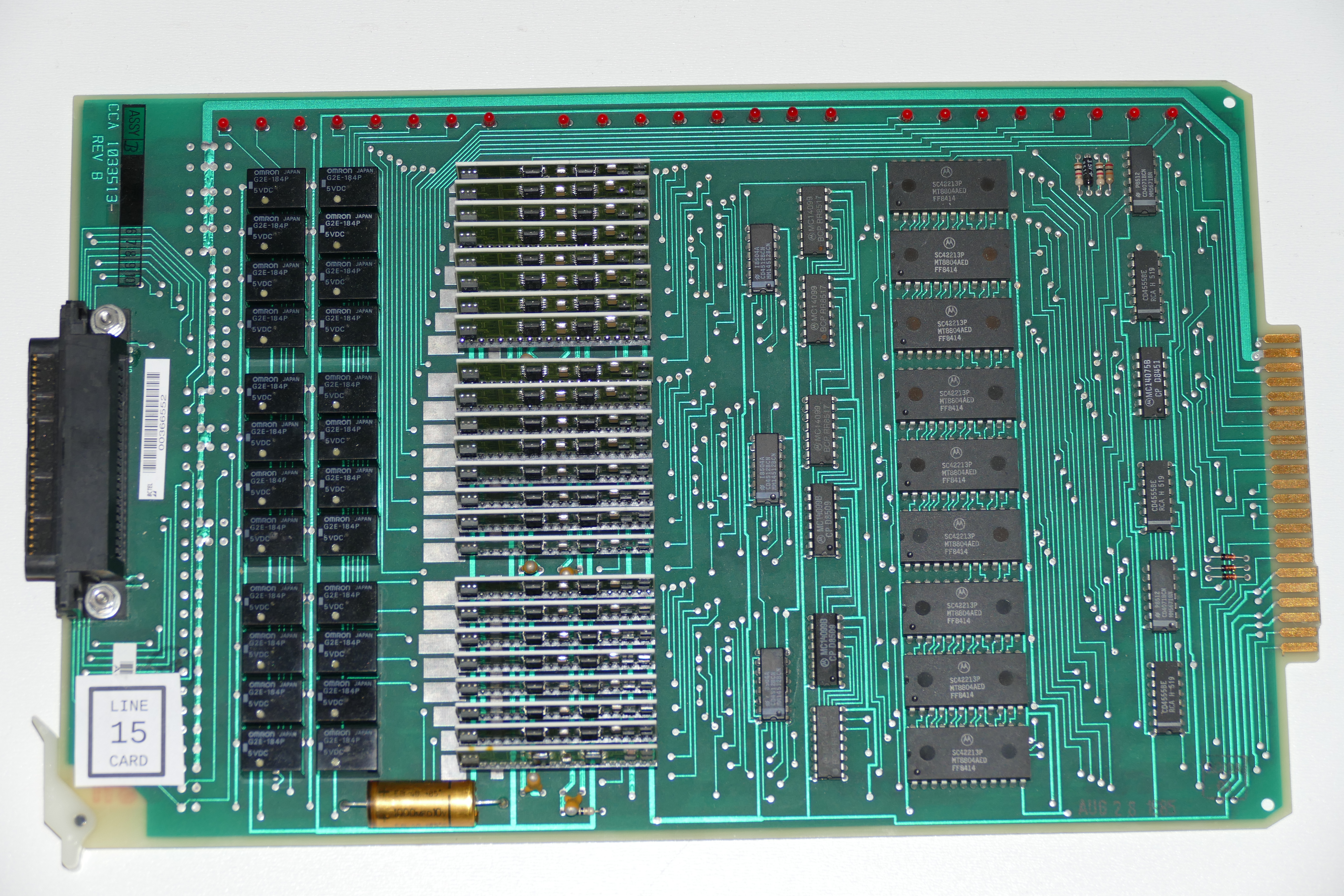
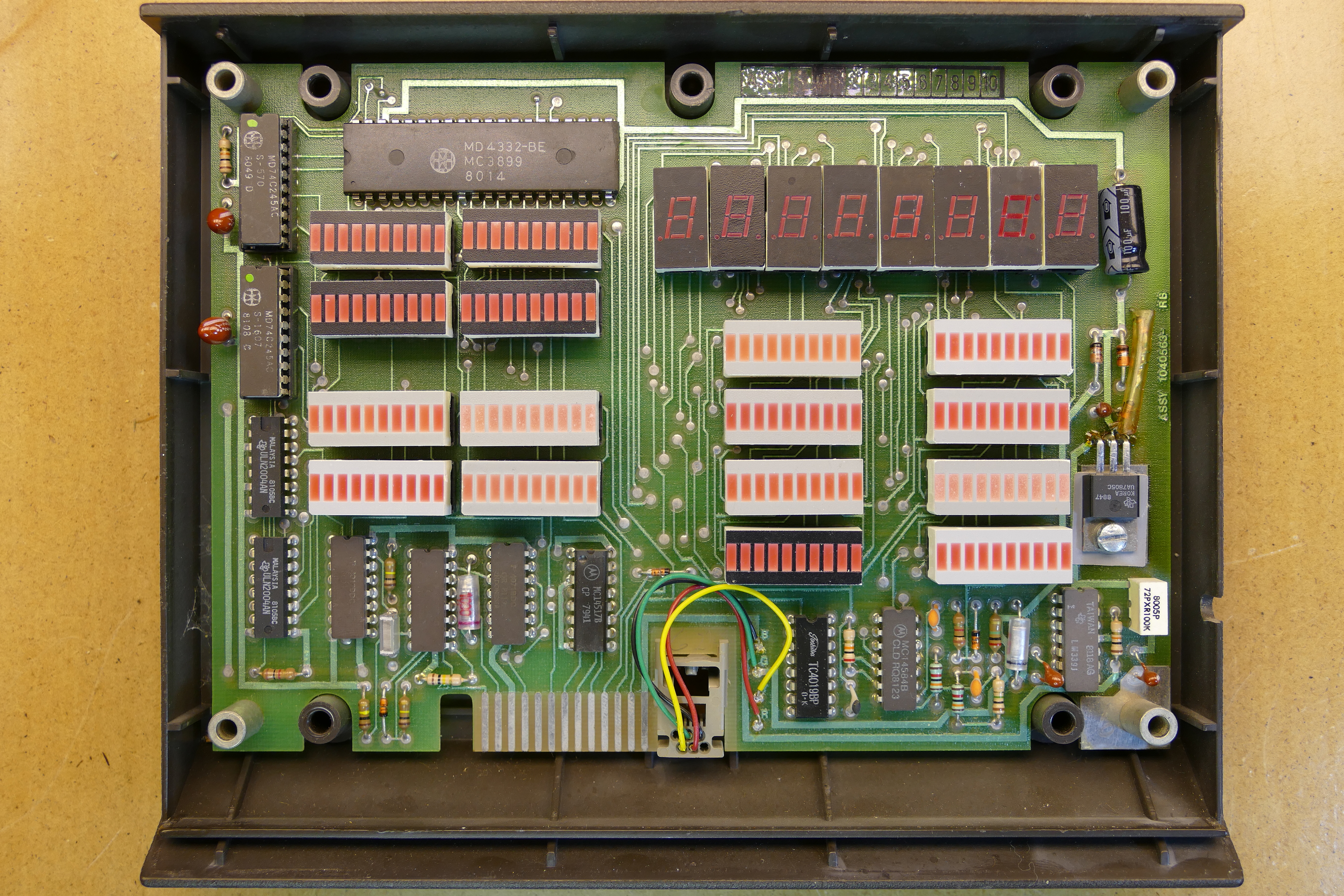
Line Cards
There are two types of line cards; ones that interface to Plain Ordinary Telephone Sets (POTS) and ones that work with Mitel's SuperSet phones.

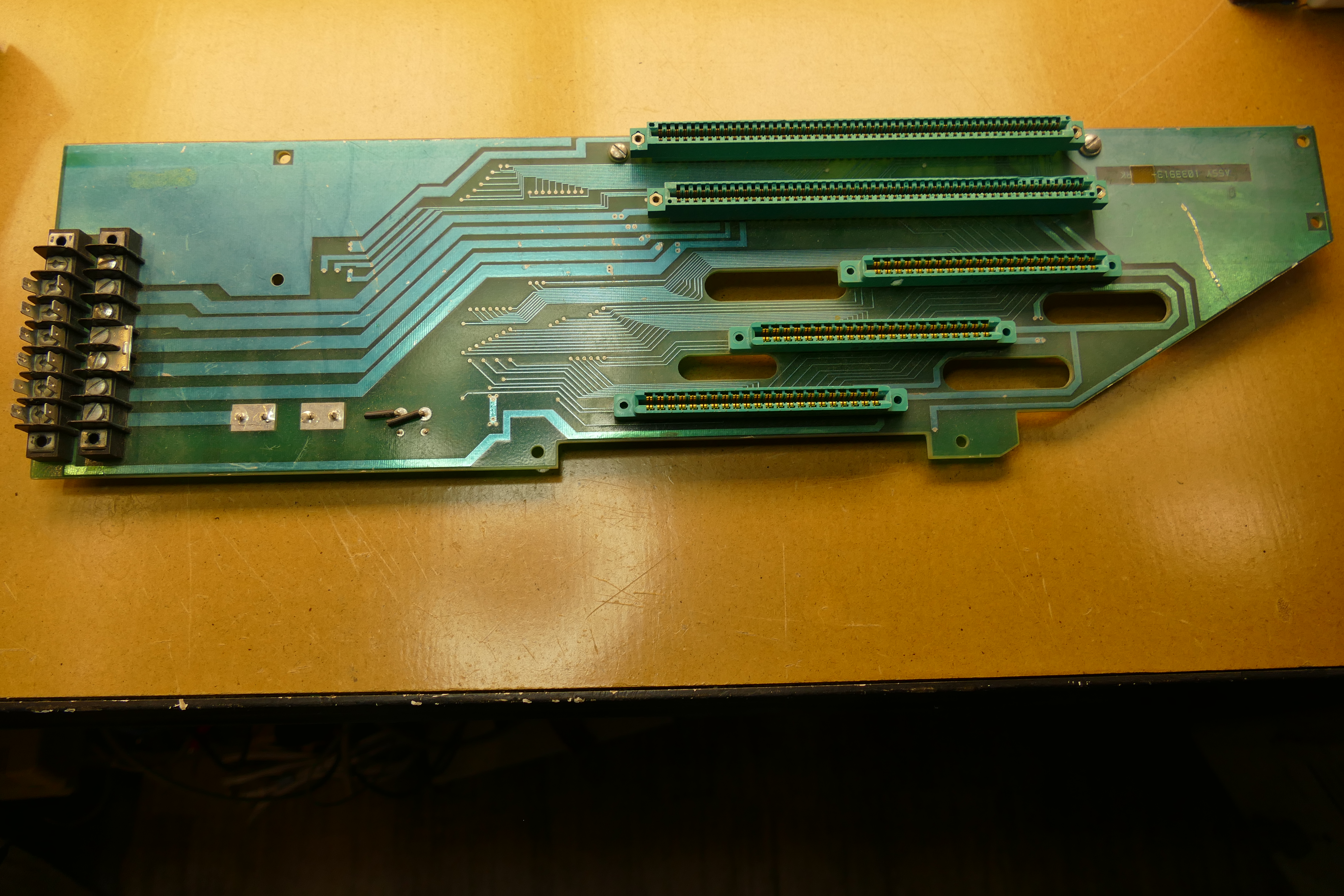
The Backplane


The Remote Display


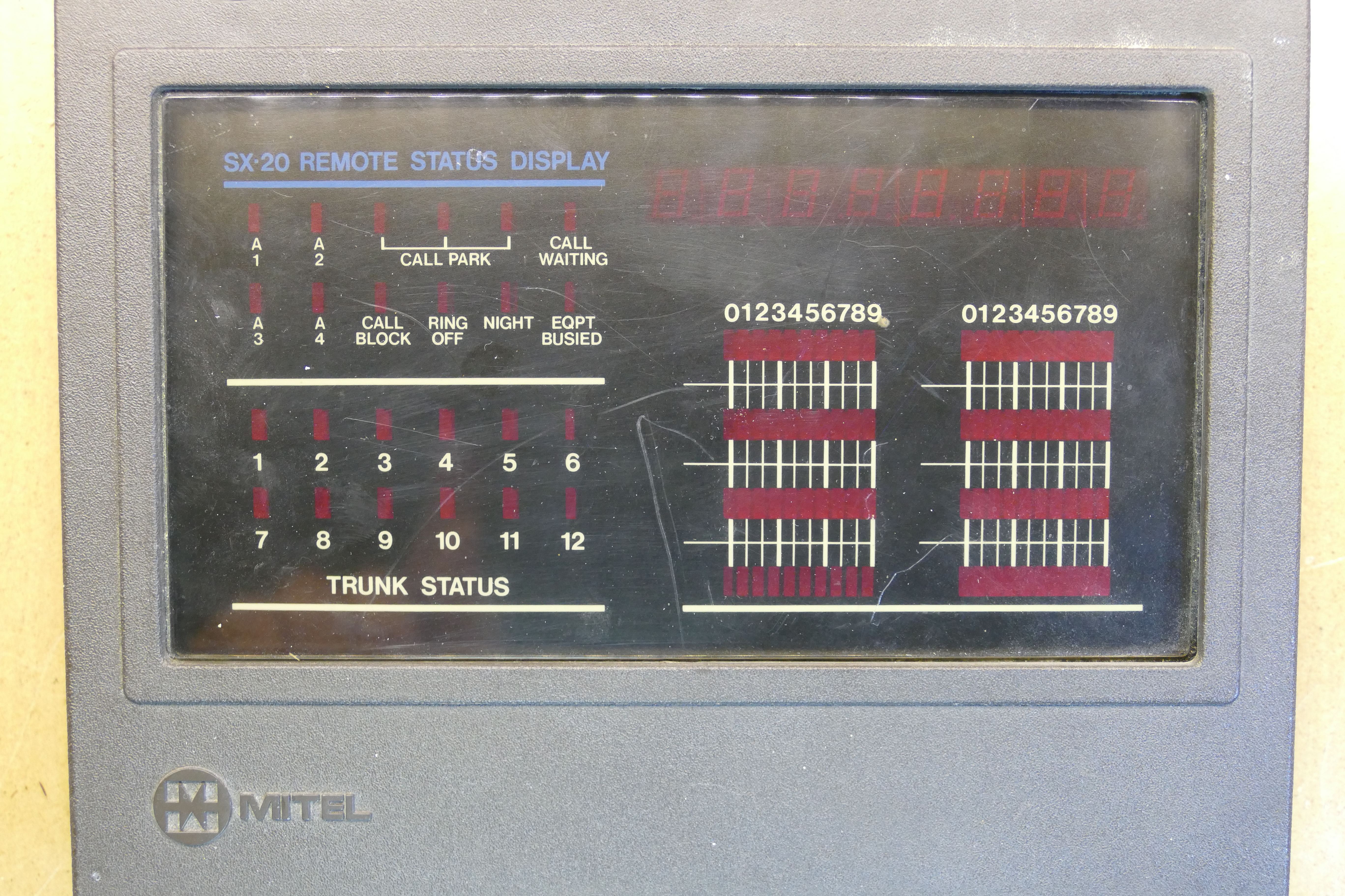

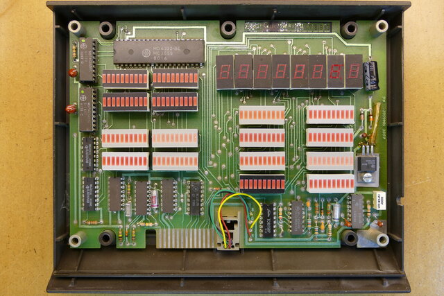
Test and Development
During test and development, I built a three-layer "cathouse" that selects one of the 24 lines:


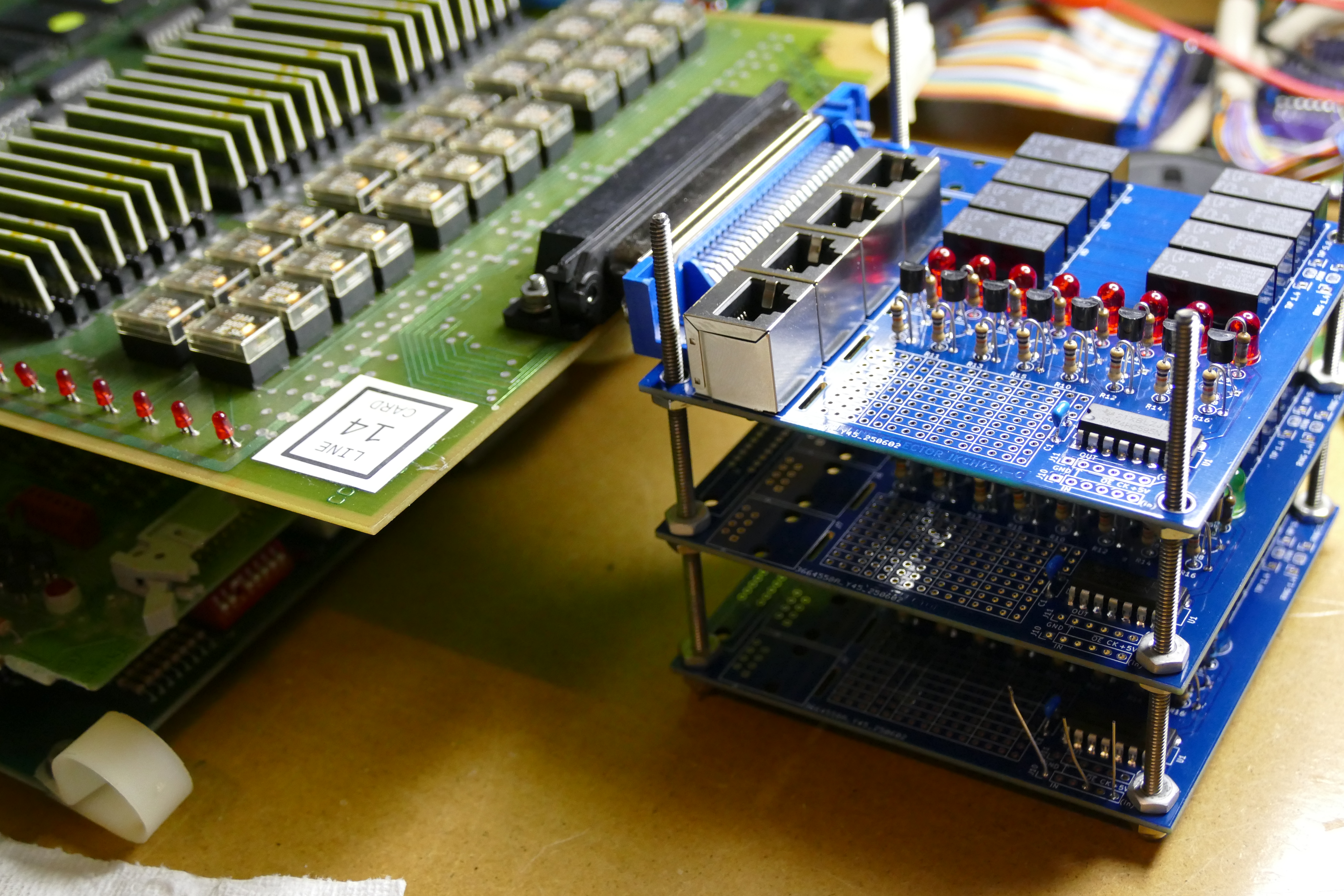
In order to simplify new software development, I created a 6809 emulator using a Raspberry Pi PICO that replaces the 6809 on the CPU card:
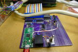

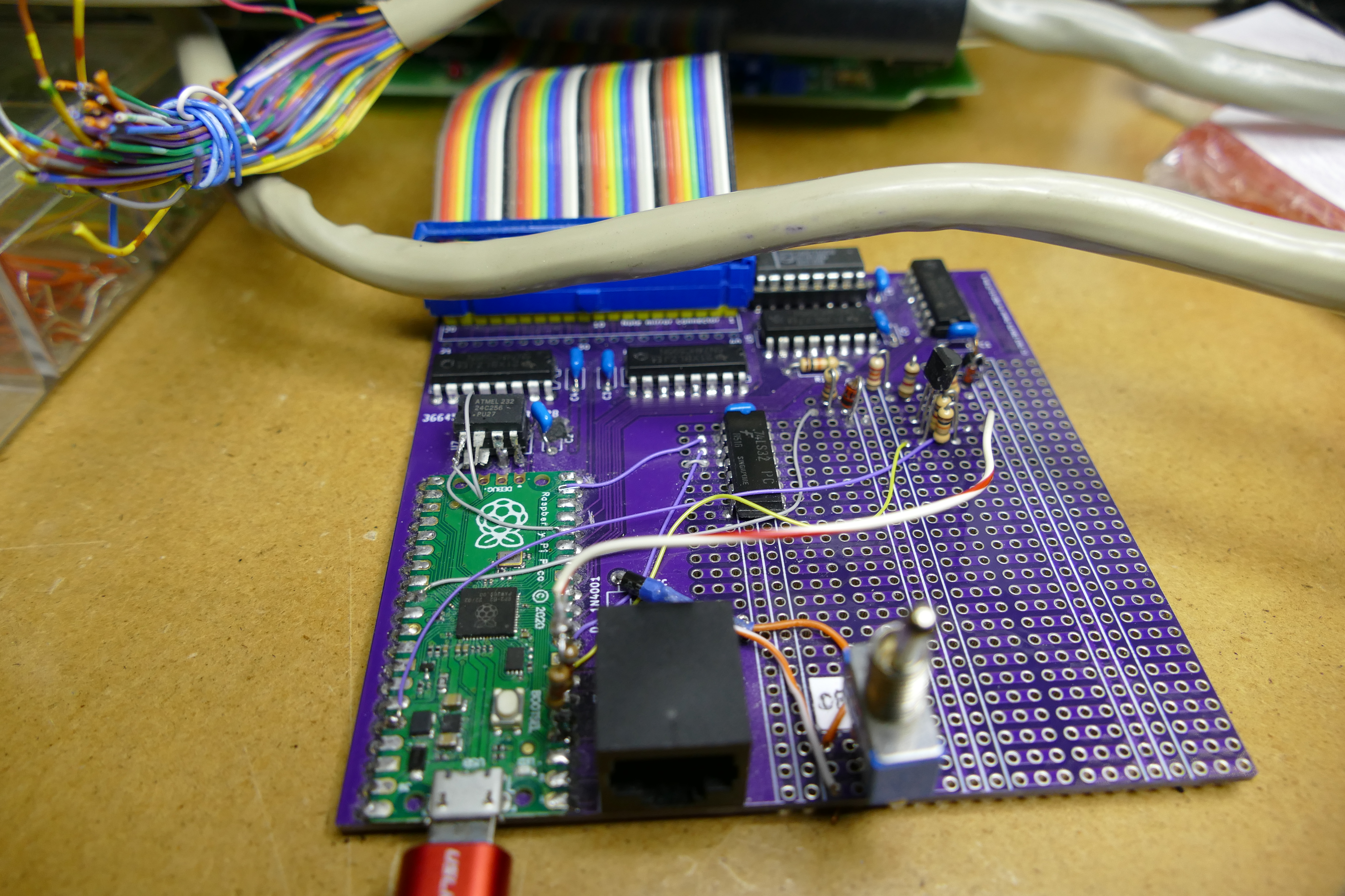

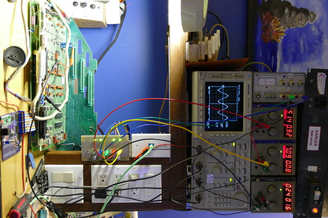
This is the bench setup during development. Note the power supplies! The SX-20 takes -24V, -8V, +5V, and +7V (as well as 90V ringing, but I didn't supply that).

Documentation
The SX-20 Generic 503 manual
PN9102-050-006-NA Issue 3 Mitel Standard Practice Generic 503
Source code
********************************************************************
*
*          PP POWER UP
*
********************************************************************
*
*  SET UP EXORCISER INTERRUPT VECTORS
*  IF MBUG EXISTS
*    THEN INITIALIZE IT
*  ENDIF
*  WRITE ALL EIGHTS TO LOCAL & REMOTE DISPLAY
*  CALCULATE PP PROM CHECKSUM (0)
*  CALCULATE CP PROM CHECKSUM (1)
*  TEST VOLATILE RAM (EXCEPT MBUG RAM) (2)
*  ZERO VOLATILE RAM (EXCEPT MBUG RAM)
*  INITIALIZE WORK AREAS
*  INITIALIZE COMMAND BUFFER FREE LIST
*  INITIALIZE HARDWARE
*  BLANK ALL DISPLAY
*  DETERMINE CONSOLE TYPE
*  RUN CP (CALL PROCESSING)
*
PPPSTR  EQU     *               START OF PP PROM
CHKSUM  FCB     0               STORE MINUS CHECKSUM HERE
        FCB     PPREV           PP REV #
        FCB     PPBLD           PP BUILD #
        FCB     PPPTC           PP PATCH #
*
PWRUP   EQU     *
        STA     NVREN2          SELECT PP RAM PAGE
        LDS     #PPSPTP         INITIALIZE PP STACK POINTER
        SEI
        LDA     MBPI.
        CMPA    #$BB            MBUG EXIST?
        BNE     PWR00           NO
        JSR     NITMB.          YES INIT MBUG
        SEI
*       JMP     PWR30           SKIP ALL THE TESTS
*
*  OUTPUT EIGHTS TO LOCAL & REMOTE DISPLAY
*
PWR00   LDA     #$01
        LDB     #255
PWR01   EQU     *
        STB     DISLOC
        STB     DISREM
        STA     DISREG
        STA     DISREG
        STA     WDOG
        DECB
        BNE     PWR01