IKCH-33 3-Input, 3-Output Arbitrary Function Generator
This board takes three inputs, and produces three independent outputs based on arbitrary boolean functions.
Motivation
I created this board because I got tired of manually wiring up simple little circuits to combine signals. For example, imagine you have a frequency source (like 440Hz), and you want to modulate it based on some input signal (so that you can make an annoying beep-beep-beep sound). The obvious solution is to connect the frequency source and the modulation signal into an AND gate, with the output being the modulated signal:
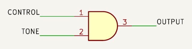
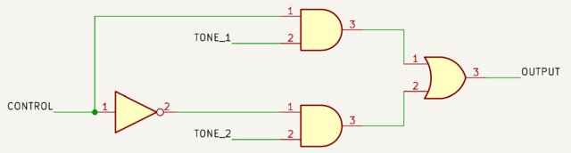
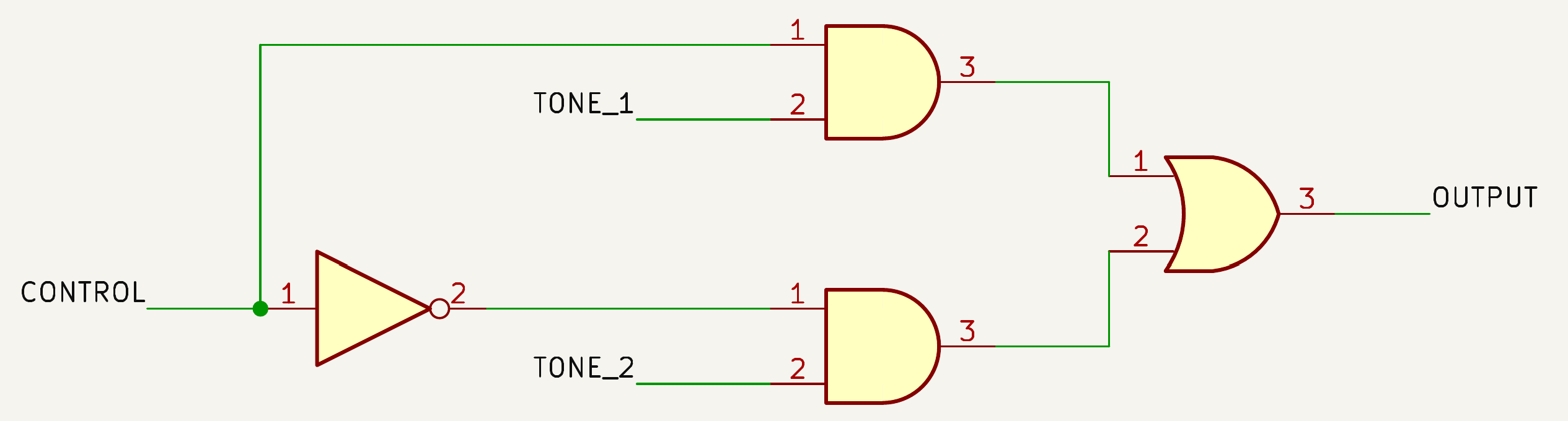
Or, you might want to select a signal. If a control signal is a zero, select the first signal; if it's a one, select the second signal. This can be used to produce the second most annoying sound: beep-boop-beep-boop.
The circuit now becomes an inverter and two AND gates; the first AND gate is connected to the true control signal and the first source signal, and the second AND gate is connected to the inverted control signal and the second source signal. Now, depending on the state of the control signal, one of the two input signals is selected. Then you'll want to have an OR gate to allow either of the selected signals to be the final output:
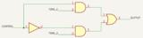
You can imagine other combinations of signals.
The hardware
You can build hardware that does this programmatically — and it's simple to do!
We'll start with a two-input version just so we're building up the conversation cleanly.
At first blush, that almost looks "too simple" — and yet, it can produce all functions of two input signals.
Let's see how.
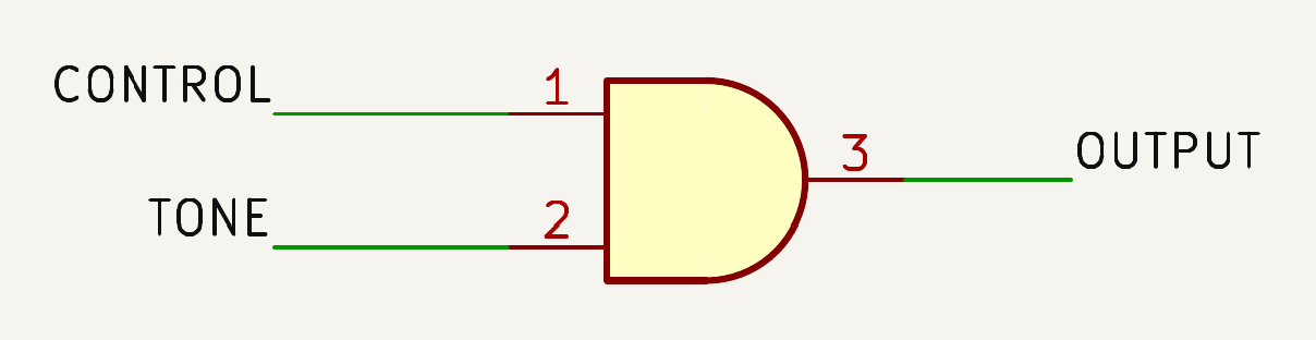
Returning to our very simple "tone modulated by a control signal", we're really just performing the function OUTPUT = TONE & CONTROL. It's a simple AND gate.
Here's the truth table:
| A | B | Y | |
|---|---|---|---|
| 0 | 0 | 0 | |
| 0 | 1 | 0 | |
| 1 | 0 | 0 | |
| 1 | 1 | 1 |
We use the standard "truth table" convention of inputs being A, B, and so on, and outputs being called Y. So, the CONTROL input is A, and the TONE input is B. The result is Y.
When the CONTROL signal (A) is off, the output (Y) is off; only when the CONTROL signal is on do we "gate" the TONE (B) signal to the output.
A programmable truth table
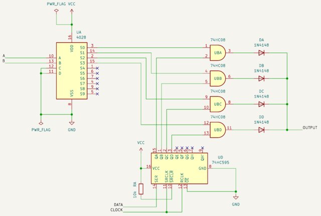
Effectively, the hardware shown above provides a programmable truth table. Notice on the left-hand side that we have the two inputs, A and B, going into the address lines of the 4028. We're using it as a 1-of-4 decoder, meaning the two inputs are decoded into one (and only one) output being active: S0, S1, S2, or S3.
Effectively, this is the truth table row.
Each of those signals enables its corresponding AND gate.
What does the AND gate have as the other signal?
It has the content of the corresponding truth table row!
So, all we need to do is program 0, 0, 0, 1 into the 74HC595 shift register. (This is what the hardware signals CLOCK and DATA, at the bottom middle of the schematic, are used for.)
Now, when the 4028 is presented with one of the four possible combinations, the circuit gates in the output!
If you want to think about it another way, what we've created is effectively a 4-entry lookup table (LUT). LUTs are standard fare in everything from programmable logic arrays to cryptographic engines.
With the hardware presented above, the 74HC595 shift register holds the content of the LUT. We've separated the "look up" aspect (the 4028 and the AND gates) from the "content" aspect (the 74HC595).
Of course, you can expand this to three (or more) inputs. You just make a bigger LUT.
Beep-Boop
In order to create the logic for our second most annoying sound, where a control signal selects one source or another, you first start with the truth table.
Here, A is the control signal, and B and C are the two tone inputs. Y is the output.
| A | B | C | Y | |
|---|---|---|---|---|
| 0 | 0 | 0 | 0 | |
| 0 | 0 | 1 | 0 | |
| 0 | 1 | 0 | 1 | |
| 0 | 1 | 1 | 1 | |
| 1 | 0 | 0 | 0 | |
| 1 | 0 | 1 | 1 | |
| 1 | 1 | 0 | 0 | |
| 1 | 1 | 1 | 1 |
Whenever A is zero, Y has the same state as B. Whenever A is one, Y has the same state as C.
All you need is a three-input LUT:
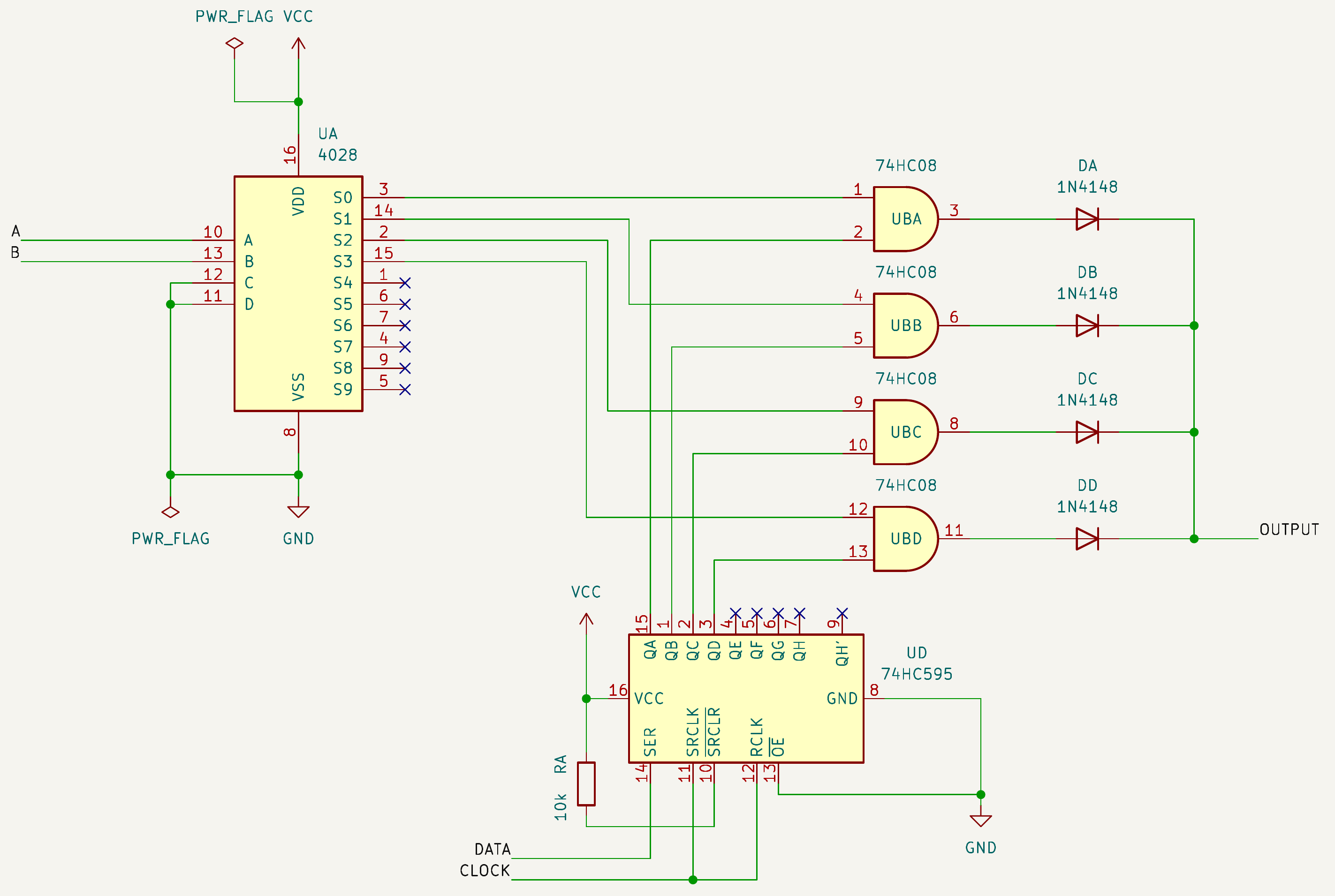
The schematic above is just an extension of the one presented earlier. It adds a C input that gates in 4 more bits from the 74HC595 shift register.
A & (-B ⊕ C)
Just to prove that this really is an arbitrary function generator, pick a more complicated function — not just a simple gate. How about Y = A & (-B ⊕ C)?
The schematic looks complicated!

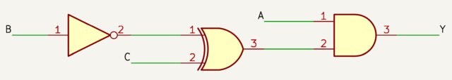
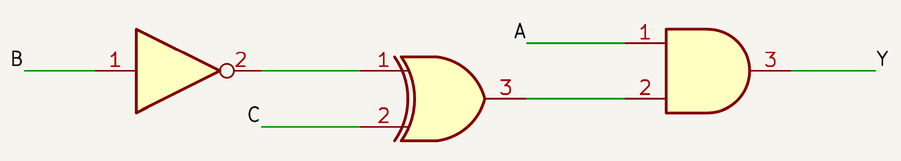
But the truth table is really just 8 rows, looked up by A, B, and C:
| A | B | C | Y | |
|---|---|---|---|---|
| 0 | 0 | 0 | 0 | |
| 0 | 0 | 1 | 0 | |
| 0 | 1 | 0 | 0 | |
| 0 | 1 | 1 | 0 | |
| 1 | 0 | 0 | 1 | |
| 1 | 0 | 1 | 0 | |
| 1 | 1 | 0 | 0 | |
| 1 | 1 | 1 | 1 |
The key insight is that the boolean function, regardless of complexity, is entirely represented by 8 bits — its truth table.
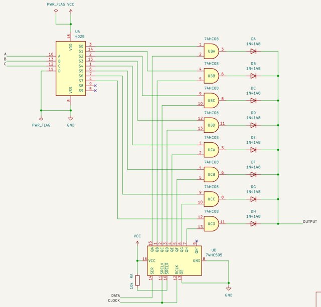
IKCH33 Board
The IKCH33 board contains three independent lookup tables, each with 8 bits. The "function" is up to the user to define; you select what the truth table looks like, and then you program the lookup table with those exact values.
To put that into a compact form, each function is represented by its binary truth table values. Thus, we can say that the boolean function Y = A & B & C is 10000000 (or 80 hex), and the boolean function Y = A & (-B ⊕ C) is 10010000 (or 90 hex).
Each function has an 8-bit code that uniquely identifies it.
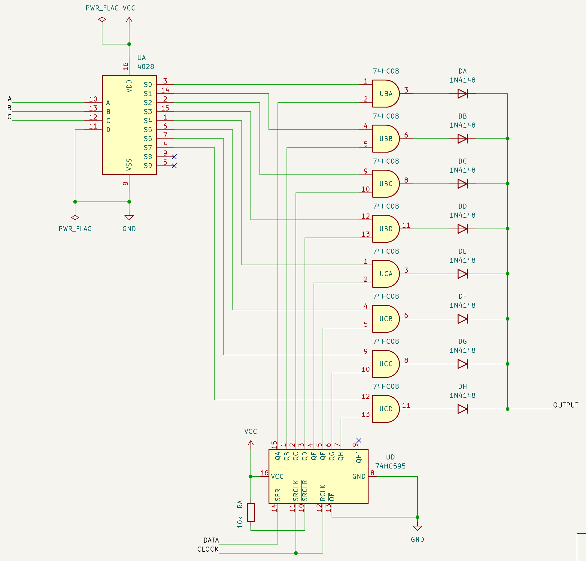
Expanding to more...
What if you wanted to make an arbitrary function generator with 4 inputs?
The truth table required for 4 inputs has 16 rows. Therefore, you'd require 16 bits of data to represent the function.
The formula for the number of rows is simply 2N. The formula for the total number of possible boolean functions is 22N (65,536 in this case).